METHODOLOGY OF THE ECOFUEL PROJECT
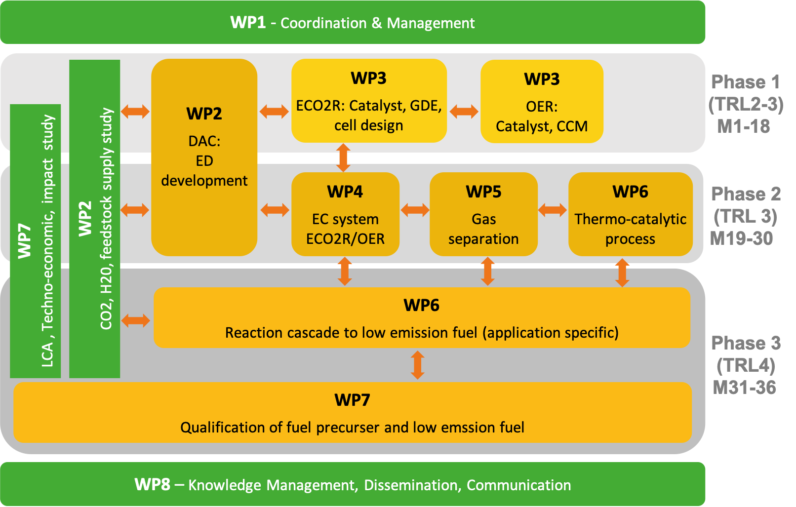
The overall 36-month EcoFuel project work is broken down into a set of distinct, interlinked R&D activities running in parallel or in sequence, on the one hand, as well as continuously running non-R&D activities, such as project management, exploitation, communication, and dissemination. The figure illustrates the overall work package structure of EcoFuel with their inpidual activities. The project work is pided into 8 work packages (WP 1 to WP 8) that will be completed over three distinct project time phases 1-3.
Non-R&D activities (M1-M36)
A range of supporting actions in WP 1 and WP 8 will be carried out throughout the project duration to ensure and improve effectiveness and optimal task execution toward goal completion. These include management, risk assessment and contingency plan conception (AVL LIST GMBH - AVL), as well as communication and dissemination activities (Pretexo).
R&D activities (M1-M36)
Phase 1 (M1-M18) – TRL 2-3
R&D work in phase 1 starts with addressing the issue of defining and specifying the chemical reactant inputs for the EcoFuel fuel production process chain. In WP 2, Axiom, SE (Siemens Energy), AVL, and FHG (Fraunhofer) will carry out collaborative analyses of the supply and purifications of CO2 and water feed stocks from concentrated sources. This task will extend into phases 2 and 3 over the entire project duration of EcoFuel (see below). Furthermore, in WP 2 Axiom will develop the sustainable, scaled-up sourcing of concentrated CO2 feeds using their proprietary Direct Air Capturing (DAC) technology. The DAC based CO2 output feed specifications serve as input parameters for the R&D activities related to the electro-catalytic conversion of CO2 in electrolysers bundled into WP 3 and WP 4.
WP 3 is involving JM (Johnson Matthey), TUB (Technical University of Berlin), UOXF (University of Oxford), and SE - is focusing on the synthesis and initial screening of new electrocatalysts for the cathodic electro-catalytic CO2 reduction (ECO2R) and the anodic electro-catalytic oxidation of water to oxygen (OER). Work on ECO2R catalysts will place emphasis on new directions regarding facet-, morphology-, and surface composition-engineered Cu-based as well as NiPx based catalyst concepts with the aim to understand, control and improve the faradaic efficiency of C2+ gaseous hydrocarbons, while reducing that of competing products at low kinetic overpotentials. The initial characterisation and screening of the kinetic catalytic reactivity is conducted in small scale liquid and custom-made in-situ mass spectrometric cells. Research on the anode catalyst is geared towards reducing and replacing noble metal catalyst components, while maintaining or lowering the kinetic overpotentials, thereby raising the energy efficiency. Strong focus is placed on a swift transfer from discovery and screening toward deployment and full single electrolyser-cell design/testing of cathode/anode catalyst formulations in small-scale ca 3-10 cm2 Gas Diffusion Electrode (GDE) or catalyst coated membrane (CCM) configurations. Down-selected pairs of successfully tested and most promising catalysts will be transferred to and serve as input for scaled up electrolysis in larger-scale GDEs carried out in WP 4 and Phase 2. Electrode and materials performance feedback resulting from electrochemical testing in scaled up cells in WP 4, on the other hand, will be passed back to WP 3 and be considered in R&D work.
Phase 2 (M19-M30) - TRL 3
Activities during Phase 2 of EcoFuel include tasks from WP 2, 4, 5, and 6.
In WP 2, Axiom will shift its focus on the costs, specifications, and the integration of scaled-up CO2 sourcing from air, which serves as input feed into inpidual scaled-up 300 cm2 electrolyser cells and cell stacks addressed in WP4.
WP 4 R&D activities are carried out by SE, TUB, UOXF, JM and BME (Budapest University of Technology and Economics) - start with the adoption of inpidual sets of catalyst pairs and GDE assemblies that were down-selected in WP 3 based on preliminary single electrolyser cell screenings. One of the objectives of WP 4 includes the decision on the most promising electrolyser cell architecture to meet the overall efficiency project goals. More specifically, SE, TUB, JM and UOXF will evaluate the more conventional “2-gap” electrolyser cell configuration against the “half MEA” configuration, where the anode catalyst is directly interfacing to the ion exchange membrane. This task also involves the use and evaluation of the most suitable types of solid ion exchange membranes (anionic and cationic) for deployment identified catalyst/electrodes and cell configurations. Note that EcoFuel does not include any discovery or development of novel ionomer or membrane chemistries or technologies. Electrolyser cell development and testing will involve membranes that are commercially available or that will be supplied in sufficient quantities by project partners. R&D work in WP 4 will further involve systematic electrolyser cell and process parameter variations at the intermediate 10cm2 active area scale. Parameters and conditions to be investigated include periodic load variations, variations in the feed compositions, anion and cation electrolyte concentration effects, as well as variations in the gas and liquid electrolyte feed rates. Time-resolved electrochemical mass spectrometry coupled with Gas Chromatography techniques will provide the resulting product space-time yields and faradaic efficiencies of inpidual ECO2R products; these quantities will be used to estimate and optimise the overall energy efficiency of the ECO2R process step. The important issue of durability and degradation of the down-selected electrodes is the sole focus of a separate task of BME within WP 4.
Important WP4 activities include the scale up of electrolyser cells from 3-10 cm2 to finally 300 cm2 (SE and JM) using input from the experimental findings obtained from the preceding WP 4 tasks. The large-scale electrolysis demonstrator will contain feed channels for gas supply/outlet and electrolyte supply/outlet as found appropriate for the electrodes developed in WP 3. The liquid/gas GDE configuration of the electrolyser cells will provide for a facile separation of all ECO2R products into gases (C2+ hydrocarbons, such as ethane, ethylene and propylene, CO, H2, CH4, and unconverted CO2) and into liquid oxygenate products that remain in the circulating liquid electrolyte stream. Scale-up of the electrolysis cell to support 300 cm2-sized electrodes will take into consideration eventual stacking to achieve a ~1kW overall system. All supporting infrastructure to ensure both smooth and safe operation of the system will be considered and implemented as part of the entire hardware assembly.
The gaseous C2+ hydrocarbon feed exiting the ECO2R electrolyser cell stack of WP 4 is the input gas feed of the subsequent gas separation process step, the design of which will be addressed in WP 5 (FHG, AVL, Axiom).
The objective of WP 5 is an energy efficient separation of the relevant C2+ hydrocarbons from hydrogen and unreacted CO2 that are both fed back into the electrolyser stack to increase the electrocatalytic CO2 conversion and energy efficiency. The gas feed exiting the gas separation unit will contain low levels of CH4 and CO. It is the design and the operating parameters of the subsequent thermo-catalytic reformer step in the EcoFuel process chain (WP 6) that will decide whether the residual levels of CO and CH4 are beneficial for the generation of the desired hydrocarbon fuel mix, or whether these components need to be separated and recirculated into the electrolyser, as well.
In WP 6, SE and FHG will carry out research to develop and optimise a novel thermo-catalytic process unit for the oligomerization/liquefaction of olefins to liquid paraffinic or aromatic products. The unit will be designed to convert C2/C3 olefin-rich hydrocarbons directly into gasoline-type C6+ hydrocarbon fuels. The C-C bond forming reactions
occur on the surface of solid catalysts packed in parallel tube reactors (PTRs). The unconventional olefin feed and the direct output of hydrocarbons in the desired molar mass range makes this process distinctly different from the conventional two-step Fischer-Tropsch gas-to-wax-to fuel process chain. The EcoFuel process step is therefore
referred to as “Olefin-to-Liquid” (OTL) process. The portion of WP 6 that falls into project phase 2 will focus on the engineering, construction, and validation of the standalone thermo-catalytic reactor.
Phase 3 (M31-M36) - TRL 4
The last phase of EcoFuel is when all inpidual EcoFuel technologies are integrated into a reaction and process cascade that turns atmospheric CO2, H2O, and renewable electricity into application-specific low-emission, liquid paraffinic or aromatic hydrocarbon fuel. This activity is covered in the latter portion of WP 6 (SE and FHG) and represents the climax of the EcoFuel project. The application specificity of the cascade operation parameters with respect to a mobility category is an important feature of the final EcoFuel Process chain. The objective of WP 6 is the demonstration of a viable and integrated electro- and thermo-catalytic reaction cascade in a lab environment (TRL4) generating on the order of hundred ml liquid hydrocarbon fuel in one test cycle. The reaction cascade is to operate at efficiencies meeting and exceeding those of competing processes. Parallel to the integration efforts in WP 6, WP 7 (AVL) activities include qualifications of precursor or low emission fuels, and thereby help adjust or modify the targeted liquid hydrocarbon fuel product.
R&D activities extending across and linking Phases
WP7 (AVL, SE, JM) addresses tasks that deal with impact-related studies. R&D activities investigate the larger environmental, societal and economic impacts of the targeted fuel production process and technologies. Focus will be placed on traditional ISO 14040 LCA studies and EC guidelines for LCA analysis included in the International
Reference Life Cycle Data System (ILCD) Handbook as well as recent EC guidelines for LCA of CCU/CCS technologies (AVL). Techno-economics involve an analysis of markets, as well as of the social acceptance of relevant technologies and their impacts (SE, JM). WP7 keeps monitoring the results of WP1-6, and 8 during the three phases of the project, and thus helps set or, if needed, adjust and modify project performance goals. Critical output of WP7 includes a comparative analysis showing the potential strengths of the EcoFuel DAC/ECO2R/thermo-catalytic reforming/refining chain, more specifically, the milestones this technology must reach to be ultimately economically competitive, environmentally beneficial, and socioeconomically advantageous.
WP2 feedstock supply studies carried out jointly by Axiom, SE, AVL, and FHG will extend across all three project phases. The studies will be tailored to the specific technology and TRL of each phase, for instance, small-scale electrolysis input feeds in phase 1, large-scale electrolysis input feeds in phase 2, and reaction cascade input feeds in phase 3.
The overall work breakdown structure with work packages of EcoFuel indicating 3 interlinked project phases over which the TRL levels are raise from 2-3 to 4. R&D activities are in blue, others in green. Arrows denote input and output of materials or information.